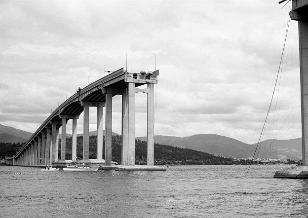
On the night of 5 January 1975, the bulk ore carrier SS Lake Illawarra allided with the Tasman Bridge in Hobart, causing two pylons and a large span of road to collapse into the river. The ship sank with the loss of seven crewmembers, along with five motorists. (© Commonwealth of Australia, National Archives of Australia, CC BY-NC-ND.)
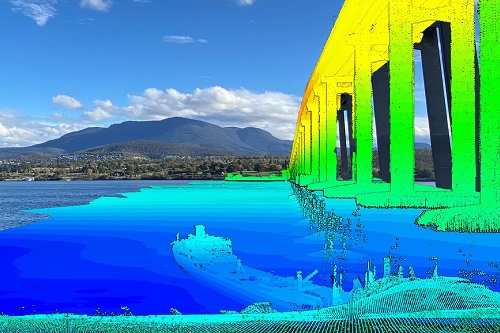
The first-ever ultra-high-resolution spatial digital twin of the SS Lake Illawarra and the Tasman Bridge reveals remarkable detail.
By Phil Vandenbossche, Chris Berry and Craig Davey, CSIRO
On the night of 5 January 1975, the 140-metre-long bulk ore carrier SS Lake Illawarra was passing under the Tasman Bridge in Hobart when it struck a bridge pylon near the eastern shore and sank. The impact caused a 127m-long section of the bridge span and two of its supporting pylons to collapse. Twelve lives were lost — seven crewmembers of the vessel and five occupants of cars that went over the edge.
While this tragic event still resonates with many Hobartians, it is often forgotten that the ship remains on the bed of the Derwent River below the bridge at a depth of approximately 35 metres. At that depth and where it lies outside the main channel, it poses no hazard to navigation. However, its presence has attracted interest from divers, boating enthusiasts, historians, research communities and others, including CSIRO.
Project concept and collaboration
In October 2021, the specialist marine Geophysical Survey and Mapping (GSM) team from CSIRO, in collaboration with industry engineering firm Jacobs, undertook an advanced survey of SS Lake Illawarra and the Tasman Bridge. While the mapping of the wreck was not a novel concept — it was first mapped by CSIRO in 2014 — the 2021 survey differed in that it produced the first ever ultra-high-resolution (UHR) spatial digital twin of the wreck, riverbed and bridge infrastructure.
CSIRO initiated the survey project with three objectives: assess the capability of some of the latest sonar technology on the market; enhance skills and capacity in the team; and provide data and visualisations for research and public benefit, including in education and outreach activities.
For this project, Jacobs provided terrestrial survey expertise and the latest laser mapping technology, while CSIRO provided underwater survey expertise, together with some of the latest underwater sonar technology. The CSIRO research vessel RV South Cape was used for the above- and below-water surveys.
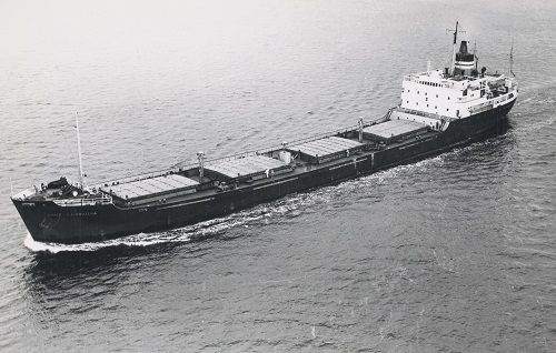
The SS Lake Illawarra (Tasmanian Archives and Heritage Office/Wikipedia)
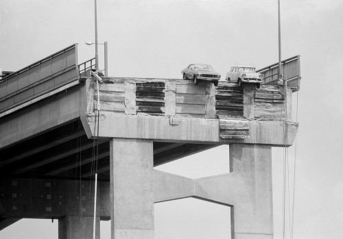
The occupants of two vehicles had lucky escapes. (© Commonwealth of Australia, National Archives of Australia, CC BY-NC-ND.)
Methodology and equipment
The survey was completed in two phases. First, Jacobs mobilised a RIEGL VMX-2HA high performance, mobile laser scanning (MLS) mapping system on the RV South Cape and conducted a UHR scan of the above-water components, consisting of the bridge, bridge pylons and adjacent shorelines. Next, CSIRO mobilised a hired NORBIT WINGHEAD i77h compact UHR multibeam echosounder and accompanying iLiDAR terrestrial scanner and conducted the underwater survey components. This included the wreck, surrounding riverbed and submerged sections of the supporting bridge pylons.
Prior to each survey, both teams performed rigorous offset measurements and pre-survey calibrations to ensure best survey practice and system performance. A planned survey grid was used to map the riverbed from shore to shore, and on both the southern and northern sides of the bridge. A smaller survey grid was then used to specifically target the detailed mapping of the wreck itself.
In addition to the vessel-based surveys, Jacobs installed the terrestrial MLS system on a vehicle and mapped the entire bridge deck (road) and approaches to the bridge.
2014 vs 2021 bathymetric surveys
In 2014, CSIRO’s survey of SS Lake Illawarra was undertaken using a Kongsberg EM2040c multibeam echo sounder. At the time, this was one of the latest high-resolution, shallow-water survey sounders available. While this was, and remains, a sophisticated industry standard shallow-water survey system, its highest operating frequency is 400 kHz. However, the 2014 survey was conducted at a nominal frequency of 300 kHz and in an equipment testing scenario, rather than a detailed planned survey of the wreck. The result of that survey yielded sonar imagery that was impressive at the time and provided the highest-known survey resolution of the wreck, with 1,407,609 soundings. The mapping attracted significant community and media interest.
For the 2021 survey, the NORBIT WINGHEAD i77h was used at a frequency of 700 kHz, more than double that of the 2014 survey, to map the wreck and associated debris in far greater detail — higher frequencies combined with narrow beamwidth results in greater acoustic resolution. The increased resolution of the mapping also benefitted from the detailed, targeted survey plan. The result was the acquisition of more than three times the soundings of 2014, with a total of 4,350,970 data points. Whilst much of the outline and large structures are common to both surveys, the 2021 survey captured the finer detail of the wreckage, including railings, port holes, the mast and numerous other small features. The results almost resemble a photograph.
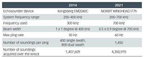
Comparison between the 2014 and the 2021 multibeam echosounder system campaigns.
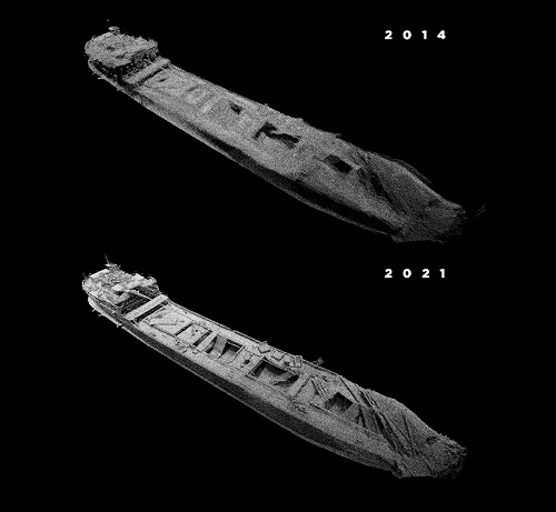
The 2021 SS Lake Illawarra survey has almost four times as many soundings as the 2014 survey.
To understand the advantages of modern underwater sonar technology, if one considers how long it would take for a diver to explore and photograph the wreck — with a narrow field of view and in dark, low-visibility conditions — one can really appreciate the benefits of this technology. The entire wreck can be mapped, in reasonable detail, with a single survey pass at 6 knots in a little under one minute! With multiple carefully planned passes, designed to ensonify all aspects of the feature, the results presented here are possible.
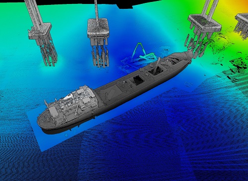
When the terrestrial MLS point cloud data is incorporated with the underwater soundings, further spatial context is provided, indicating precisely how the shipwreck is orientated and where it rests with respect to the bridge and adjacent eastern shoreline.
Production of the digital twin
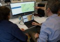
At the completion of the survey, Jacobs and CSIRO independently performed various phases of data processing and cleaning to remove unwanted ‘noise’. The dataset was also reduced to a common spatial coordinate system (GDA 2020, MGA55) and vertical datum (AHD: Australian Height Datum). CSIRO performed much of its bathymetry data processing and visualisation using a combination of industry standard software suites including Teledyne CARIS HIPS and SIPS, QPS Qimera and Fledermaus, and Pointerra3D.
Once completed, CSIRO combined both the surface and subsurface data to create a combined point cloud dataset. The resulting 3D imagery of the merged digital twin products are featured here.

Use and utility of the digital twin
The digital twin is important in spatially capturing not only the wreck itself, but also the surrounding environment including the Tasman Bridge, the riverbed between the eastern and western shorelines and sections of the shoreline too. While this provides a holistic conceptualisation of the wreck and its setting, each survey point is precisely spatially referenced and therefore can be used for accurate measurements. This opens an avenue for researchers to assess the condition of the wreck, associated features and surrounding riverbed. From an engineering standpoint, the terrestrial laser data of the bridge provides a wealth of data that is fundamental for any future bridge infrastructure planning, upgrades and monitoring purposes.
CSIRO expertise and capabilities
CSIRO has diverse expertise in its marine GSM team, comprising certified hydrographic surveyors, geophysical surveyors, acousticians, GIS specialists and data management professionals. The team primarily supports the CSIRO Marine National Facility and the advanced ocean research vessel, RV Investigator. However, GSM also undertakes shallow water mapping and survey projects through the Shallow Survey Facility (SSF). The SSF collaborates with researchers and stakeholders nationally on projects of varying scope, from renewable energy developments to habitat mapping projects and everything in-between.
Acknowledgements
CSIRO would like to thank Paul Digney and Jacobs for partnering on this project. Our thanks also extend to internal collaborators, including Dave Kruse (Master of RV South Cape) and Matt Marrison (CSIRO Corporate Affairs). We also acknowledge the CSIRO Engineering and Technology Strategic Project Program for supporting this project.
This article was first published in the Oct/Nov 2022 issue of Position magazine.
Stay up to date by getting stories like this delivered to your inbox.
Sign up to receive our free weekly Spatial Source newsletter.