This article was was written by Mohsen Kalantari, Steven Chau and Don Withanage of Faramoon, and originally published in Issue 93 of Position magazine. Mohsen Kalantari is a Senior Lecturer and Associate Director at the Centre for SDIs and Land Administration at the University of Melbourne, and a co-founder at Faramoon. Steven Chau and Don Withanage are fellow co-founders at Faramoon.
Demand for Building Information Modelling (BIM) services is growing ferociously, with the worldwide demand projected to reach a value of $US18.8 billion by 2024.
Demand for BIM services within the surveying and spatial industries is also expanding as BIM suites begin to integrate more tightly with geographic information systems (GIS). Applications of BIM within these industries are many and varied, but usually include scanning existing buildings and infrastructure facilities with LiDAR, then modelling the scans into 3D objects in BIM-compliant formats.
Completing the scanning is just the first part of the story, and can often be completed much more quickly than the modelling phase. An average single storey residential building can be scanned in around half a day, and using an appropriate computation setting, a registered point cloud produced in a couple of hours. More cumbersome and monotonous is the process of converting registered point clouds into models compliant with standards used in architecture, engineering, construction and urban planning sectors.
This is a time-consuming process. Operators need to trace over the individual components of the buildings such as walls, doors and windows to model their geometry. Some software solutions provide some level of automation to facilitate the geometric modelling of the building components. For example, planar surfaces are recognised automatically, so the modelling of planar surfaces such as walls are undertaken more quickly. After the basic geometry is modelled, the components need to be enriched by adding attributes such as type and thickness of walls.
An automatic solution
Over the last two years, the authors have investigated this workflow, aiming to develop a fully automated solution for converting scans into BIM-compliant models, so as to remove the manual processing and intervention needed in the modelling step. We analysed the current practices and various workflows associated with currently available software solutions, and their underlying techniques. Based on the findings of the study, we have designed and developed an automatic technology that takes point clouds of building interiors and converts them into 3D models that conform to international standards – without requiring any manual input. Below we’ll walk through the key stages of processing that our technology performs automatically.
Step 1: Structuring point clouds
Point clouds generated through the laser scanning process can be either unstructured or structured. In unstructured point clouds, the spatial relationship between points representing real-world objects is not reflected in the structure of the file that contains the point cloud. A comparison with raster models aids understanding here. Raster data models define the spatial proximity of values by using a regular grid, in which the same number of columns and rows are used to store the values in each cell. Unstructured point clouds can be stored in an array that has millions of columns and only one row.

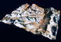
A CityGML-compliant model built automatically from scanned output.
To be able to process point cloud data efficiently and extract information from it, it is essential to structure the data. Spatial proximity operators and analysis are vastly more effective and efficient on structured data. For instance, ‘nearest neighbour’ analysis methods – to analyse variation of the density of the points over a particular space – will execute far more efficiently on structured data than they will on the unstructured data. In the structured data, the space for performing specific processes can be delimited, while with unstructured data, it is necessary to process all of the points sequentially.
Step 2: Filtering
As with any measurement device, sensors that generate point clouds may present noise and outliers as false points. Noises and outliers are generated by a combination of many factors, including the type and design of the LiDAR sensor, scanning conditions and the environment being scanned. Measurement errors, sudden motion of the sensor, geometrical discontinuities due to occlusions and varying densities across the scanned space are some of the sources contributing to the generation of false points.
Removing this noise and any errant outliers from the meaningful by filtering is essential for accurate, usable results. Methods for filtering including techniques that consider density, distribution and depth of the points in certain clusters, distance between the points, or a combination of these factors. For instance, in distance-based methods, all points with mean distances are outside of an assumed distance mean and standard deviation are considered as outliers and removed from data.
Step 3: Recognition
After removing false points from clouds, point clouds are subdivided into clusters to extract building components from them. Depending on the level of detail required in a BIM, individual components are to be recognised. For example, in the case of a multi-storey building, each level must be recognised separately to extract the planar view of each storey before further details on each storey can be recognised, such as floors, ceilings, walls and doors.
There is a range of algorithms and techniques that can be used for segmenting and recognising components of the buildings. For example, to identify an object, statistical algorithms are provided with an input point cloud alongside a mathematical model of the object to be recognised. The model is then fitted to the different areas of a point cloud, as the degree of confidence in fitting is evaluated.

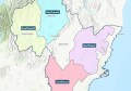
An IFC-compliant(left) and CityGML-compliant(right) model built automatically from scanned output.
For example, to find a wall, the model of a plane is provided to the algorithms. The algorithms make a subset of the given point cloud by randomly selecting a fixed number of points from the cloud. They then calculate the coefficients of the shape which best fits the sample of points. Then, they check all the other points in the cloud against this model to separate the inliers and the outliers. This consensus of the entire cloud to a model built from randomly selected points is recorded – an iterative process that is repeated several times. This yields a shape which has the highest consensus from all the random samples.
These algorithms are robust and return the best parameters, even when a significant portion of the dataset is outliers. In cases where the wall has a protruding section, or the ceiling has an elevated portion, the algorithm can find planes that fit most of that surface.
There are also machine learning methods that are used to recognise building components. In these methods, recognition systems are built, so objects are identified by learning from past recognition. In these approaches, models of building objects to be recognised are stored and labelled in an inventory called the classification database. Then, algorithms that learn are used to recognise new examples of the building objects from the existing objects that are found in the database. For modelling buildings, the classification database is compiled and sourced from Computer Assisted Design (CAD) or BIM files.
Stay up to date by getting stories like this delivered to your mailbox.
Sign up to receive our free weekly Spatial Source newsletter.
The existing models are also enriched by creating appropriate representations of building components by a human operator. In the clustering and extraction process, if a feature is recognised that fits an object in the database, it is then added to a training dataset so the algorithms can learn from the new addition. Then the addition is inserted into the classification database for future use. If the objects are not recognised a manual classification is undertaken, and the result is added to the classification database.
Once a group of points is recognised as an object, all points that lie on this object are kept, and the remaining points are discarded. As a result, at the end of this step, a set of known objects represented by point-clouds are stored.
Step 4: Modelling
After the objects are recognised, they are converted into appropriate geometric objects and structured into the required format. For example, after a cluster of points is recognised as a wall, a convex hull algorithm is used to compute a surface representing the wall by giving the extreme values of the edges in the point clusters. Also, to extract the wall thickness, point clouds taken from both sides of the wall are needed. If the points cloud represents the complete interior of a building, the thickness of all the interior walls can be modelled.
Step 5: Implementation
We’ve successfully implemented this workflow, by which point clouds of building interiors are automatically processed, and architectural components including ceiling, wall, door, windows and openings are automatically recognised, extracted and converted into semantically-enriched 3D model in two international data standards: CityGML and IFC.
This implementation can also automatically generate floor plans in planar views. Our research indicates that, depending on the level of detail expected in the 3D model, this process can be up to 100 times faster than the manual process, with a relative discrepancy modelling accuracy between 2 and 5 percent. This has the potential to greatly increase the productivity of surveying and architecture industries in generating BIM and 3D models.
This technology is now commercially available through Faramoon, a startup supported by Translating Research at Melbourne (TraM), a program designed to accelerate commercial insight for researchers at the University of Melbourne. Faramoon is also sponsored by a City of Melbourne (CoM) startup grant to support the integration of the technology to a cloud-based infrastructure to provide this technology outside Australia. The technology is licensed to Faramoon from the University of Melbourne.